Contact person:
Shi Guoxi (General Manager) Tel: 13884663303
Wang Hongzhan (sales manager): 18865577323
Telephone\/Fax: 0535—6371732
Email:sdytruixing@163.com
Address: No. 10, Xiamen Street, Development Zone, Yantai City, Shandong Province

Overview and main uses:
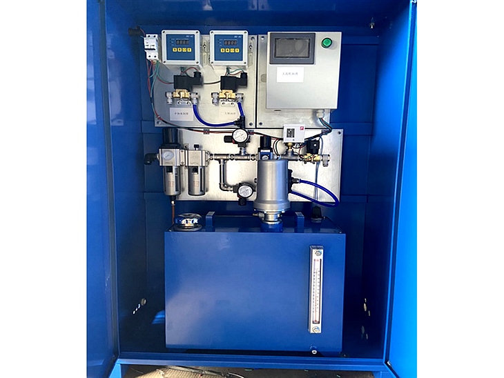
The open gear jet lubrication system is suitable for the lubrication of large gear pairs in the metallurgical industry, mining, concrete, steel, power engineering and other fields, such as: ball mills, slag scoopers, dryers, rod mills, cement rotary kilns, etc. The total width of gear lubrication ranges from 50mm to 1.06m. Depending on the total width of the gear, 1 to 8 nozzles can be selected to form a system to achieve better lubrication effects. The open gear system is divided into a 2-line spray system and a single-line spray system. According to the size of the oil storage barrel, it can also be divided into two types: built-in oil barrels and external oil barrels. This system uses PLC processing control, with free design functions of work and time intervals. The work monitoring equipment is working normally and releases alarm signals in time. This system The system is characterized by strong working performance stability, simple design, and does not require constant maintenance by staff.
Working principle and equipment composition:
1. Every time the gear starts to run, the system enters the first cycle and starts oil supply.
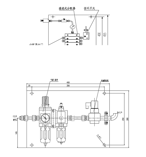
2. When the second cycle reaches the set time, the electronically controlled timer reaches the set time, and the two solenoid valves that control the air path open. The pump starts to work, and a certain amount of lubricant is transmitted from the multi-way valve to each nozzle. Air passes through the air tube to the nozzle, atomizing the lubricant and starting spraying.
3. The pump continuously transports lubricant to the oil pipe. When the time controller reaches the value preset by the electronic control, the solenoid valve that controls the pump air source turns off.
4. After the pump stops discharging oil, the solenoid valve that controls the air source of the nozzle will continue to ventilate, allowing the system to continue blowing. The time is adjustable within 99 seconds to avoid nozzle clogging. When the back-blowing action of the system is completed, the system will stop working. Until another cycle starts again.
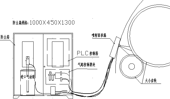
Equipment composition: Single line spray equipment system diagram


Nozzle installation specifications, dimensions and standards:
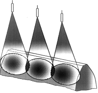
The installation position and angle of the nozzle rod on the open gear shaft protective cover have a great impact on the lubrication effect of the gear shaft. Under normal circumstances, try to spray the oil mist on the meshing surface of the pinion, but it must be under pressure On the meshing surface, install it reasonably according to the standards shown in the figure below:


The spray angle is 30 degrees, and the spray spacing can be adjusted on site! The distance can be extended appropriately.
If the gear shaft needs to rotate forward and reverse, the nozzle should be installed independently in the two rotation directions. If the nozzle can only be installed on the lower half of the gear shaft, care should be taken to prevent the grease on the gear shaft from splashing on the nozzle head, which will affect the normal function of the nozzle. Work.
Equipment working instructions:
Add appropriate 10% lubricating oil to the lubricator in the air line of the pump, and adjust the pressure regulating valve so that the pressure in the air line is 0.28 MPa.
Disassemble the joint between the pump oil supply pipe and the valve block, and then start the pump until the pipe is filled with oil. You can manually stop the pump by electronic control and reconnect the joint between the pump and the valve block.
The sequence of movement of each plunger in the distributor is determined by the last work result. Each plunger must complete its action in detail before the other plunger will move. The cycle switch sends a signal after each cycle. The solenoid valve between the pump and the distributor can adjust the flow of the main oil line and thereby control the time of the system operation cycle. If the cycle is too fast, it will cause too much oil on a certain surface of the gear shaft.
Before the system starts working, in order to cover the gear shaft surface with an oil film, the gear shaft must be pre-rotated and the system must continue to spray for a certain period to achieve the desired effect. This is because the design of this system is mainly to compensate for the loss of lubricating oil.
Adjust the air pressure of the spray air circuit to be between 0.42 MPa and 0.56 MPa, so that the system can reach a better operating condition.
The frequency of system spray is related to factors such as the linear speed of the gear shaft and the lubricant. The starting frequency is usually 180 minutes per time for ball mills. For some low-speed gear shafts, such as the external gear shaft of the rotary kiln, it is 360 minutes per time. minutes. The final frequency depends on the rotation frequency of the gear shaft. When it is visually inspected that the surface of the gear shaft is basically covered with an oil film, then adjust to slow down the frequency.


